|
|
| Steering Column Freshen Up |
| |
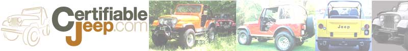
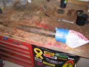
After getting everything apart, cleaned up, painted, and all the parts that
were ordered up came in, we were able to put this back together. I laid out all the parts to make sure I had everything.
Since I got this column from eBay and it wasn't all there, I had to make sure I had all the necessary parts. Once that
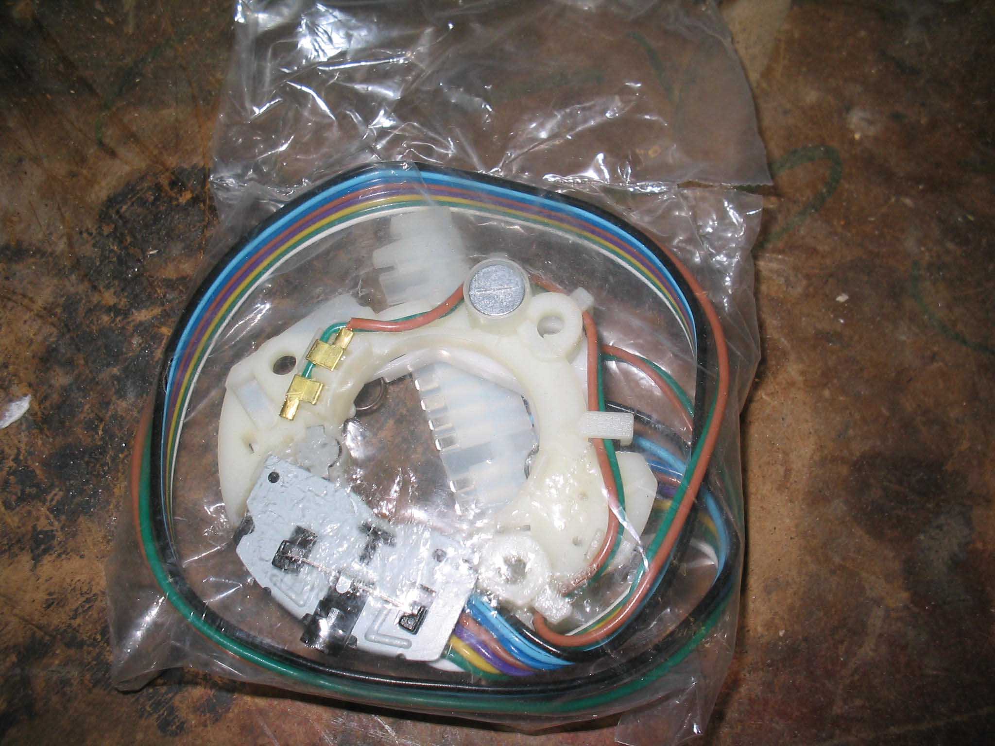
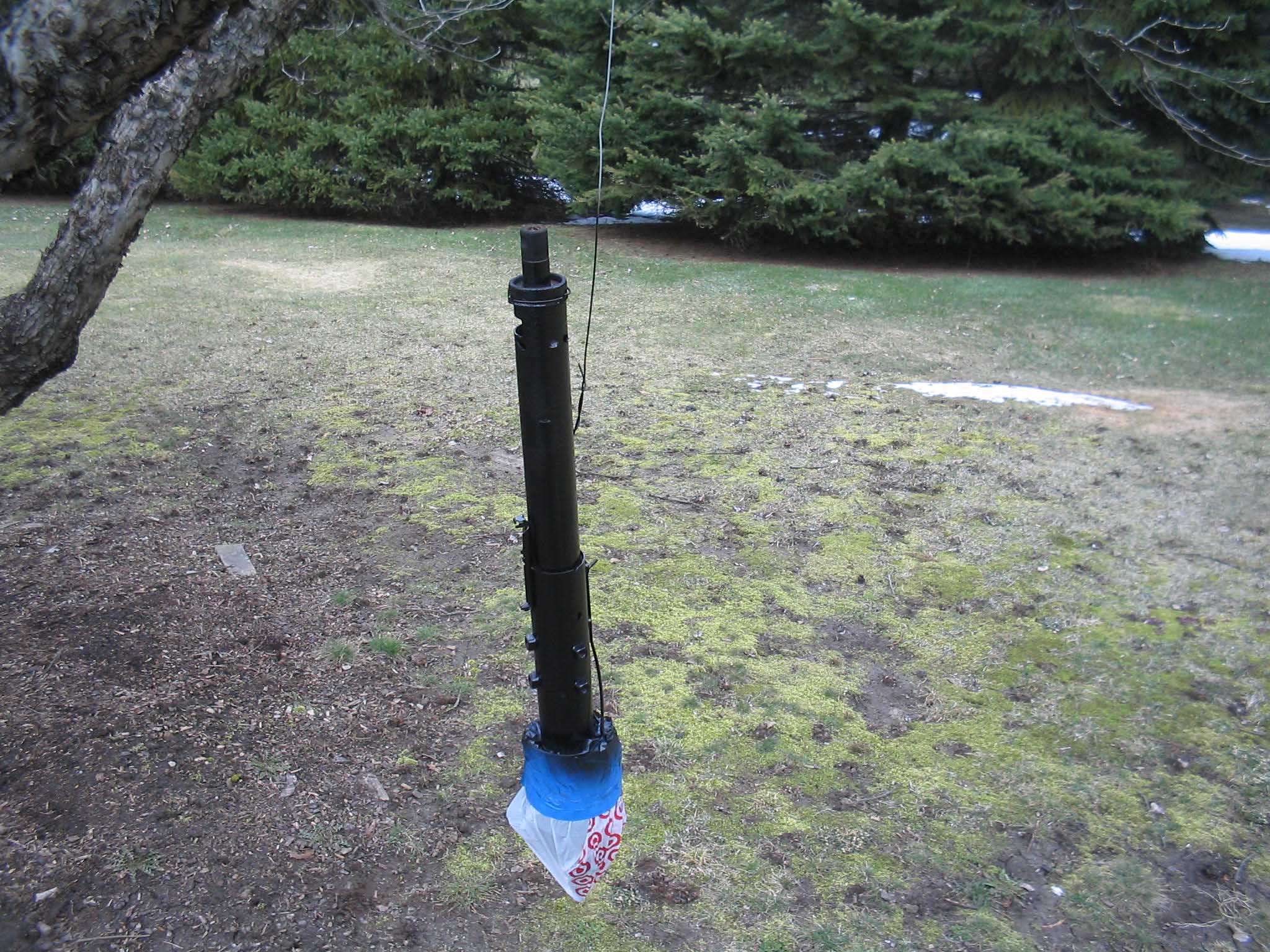
was confirmed, I taped up the plastic column and got it ready for paint.
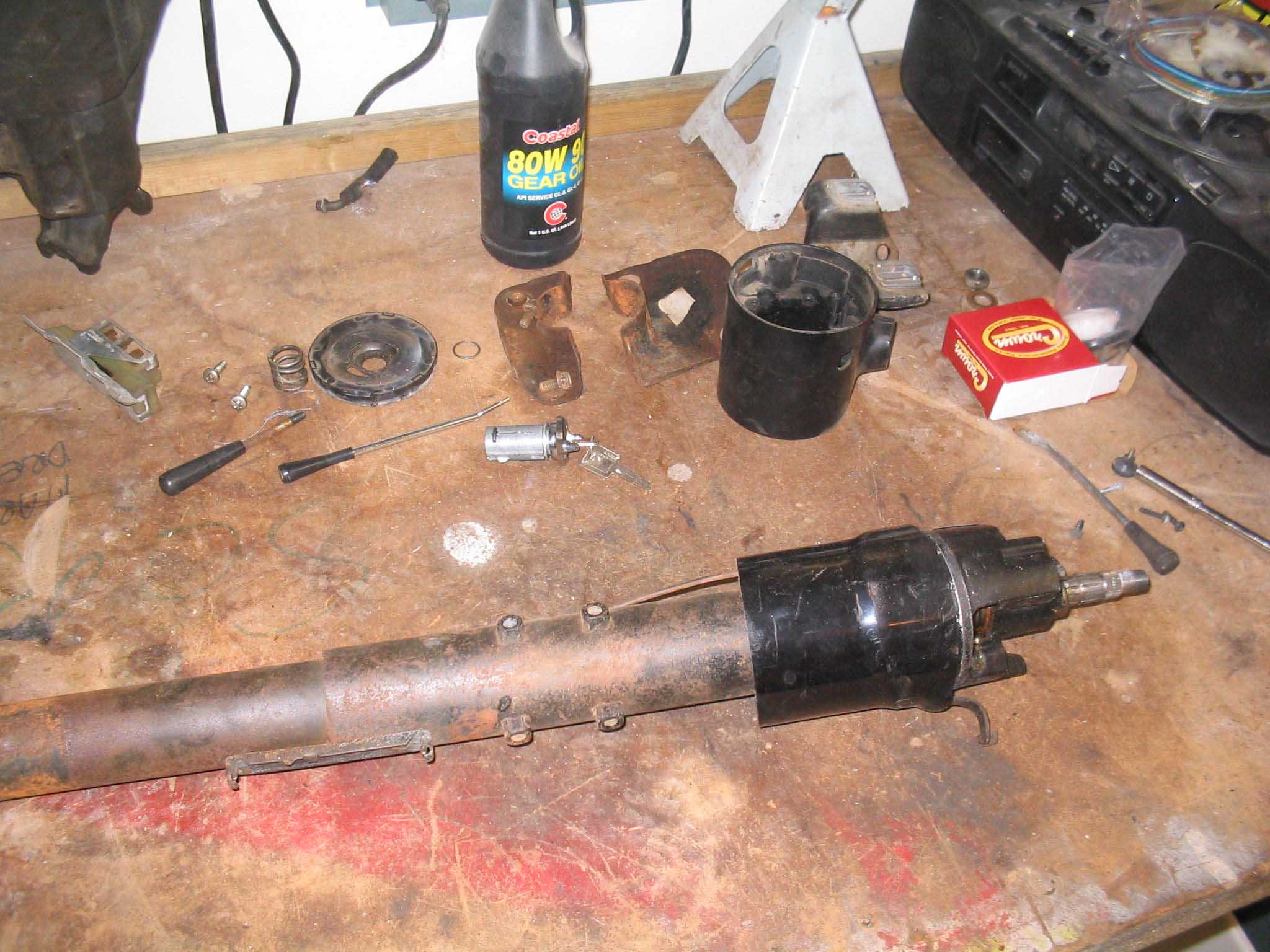
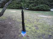
A wire brush on the drill got it cleaned up and I stuck it on the tree and gave it a few coats of black rust proof
paint. I also got the wiring turn signal switch in that I was waiting on and with the paint dried, I was ready to get
it back together.
|
| |

|
|

|
|
| |
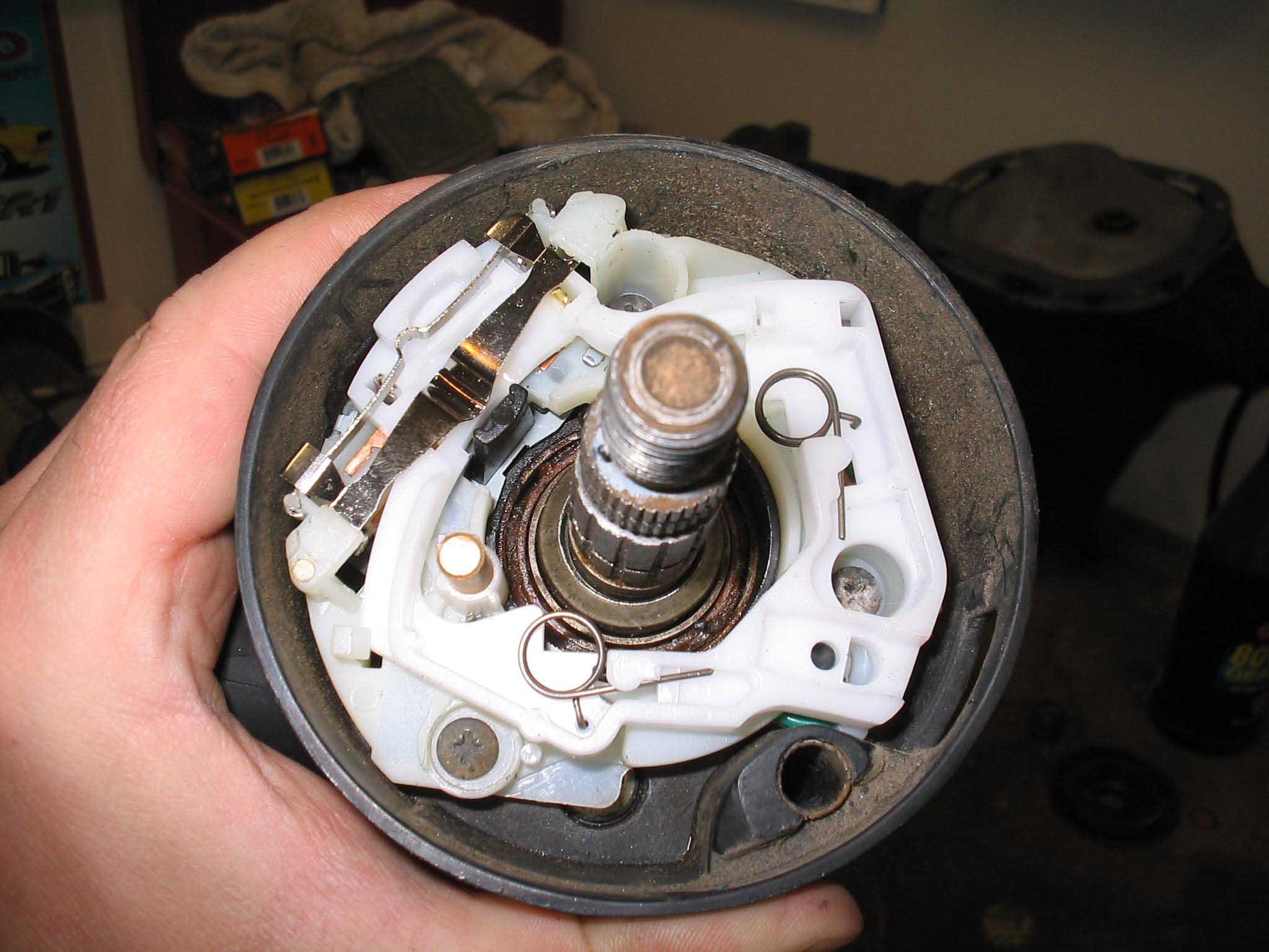
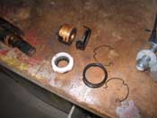
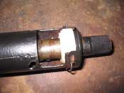
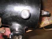
I first took apart the lower bearing to replace it. I did find something I hadn't seen
before and that was a fully brass bearing. It didn't appear to be in bad shape, but I had a brand new bearing, so I
went with the new one. I will hold onto the brass one for future use.
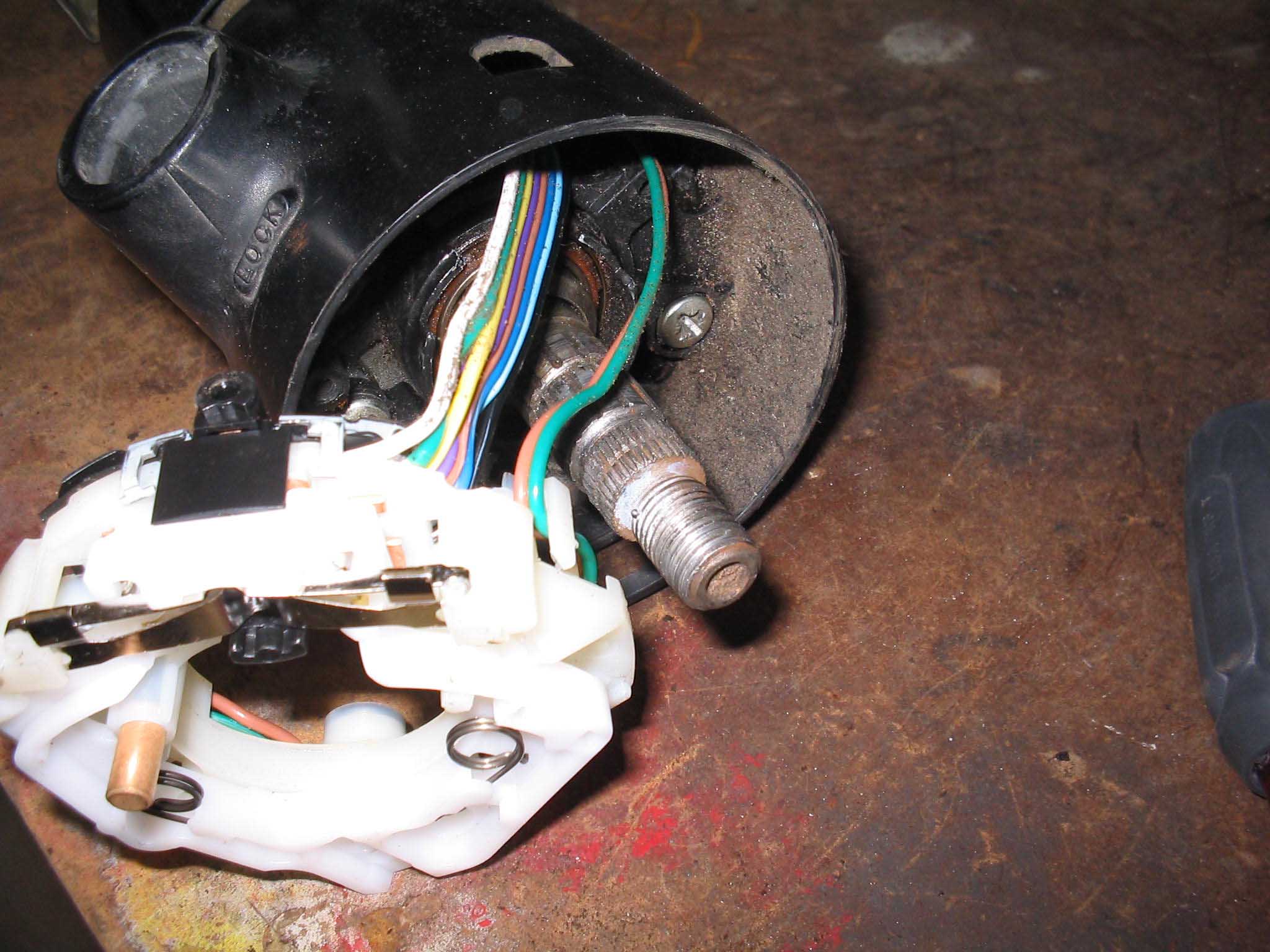
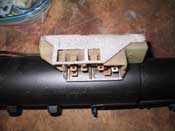
With the new bearing in place, I was able to put back on the ignition switch connection. Make sure you connect up
the key release mechanism underneath this. With that in place, thread the turn signal switch into place. You have to
fish the connection down the shaft and get it through. It is a bit of work to do this, but it should go pretty easily.
|
| |
|
|
|
|
| |
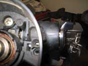
I realize the pictures are a bit out of order with this next section, but with the
wire bundled threaded through, you can put the key lock cylinder in place before you secure the turn signal switch
in place with the 3 screws that came out of the column when you disassembled it.
With the lock cylinder in place, you can put the turn signal switch in with the 3 screws and put on the hazard signal
by screwing it in by hand. If you have any issues with the lock cylinder, you sometimes have to take the key out and
then put it back in to make sure everything is aligned just right.
|
| |

|
|
|
|
|
|
| |
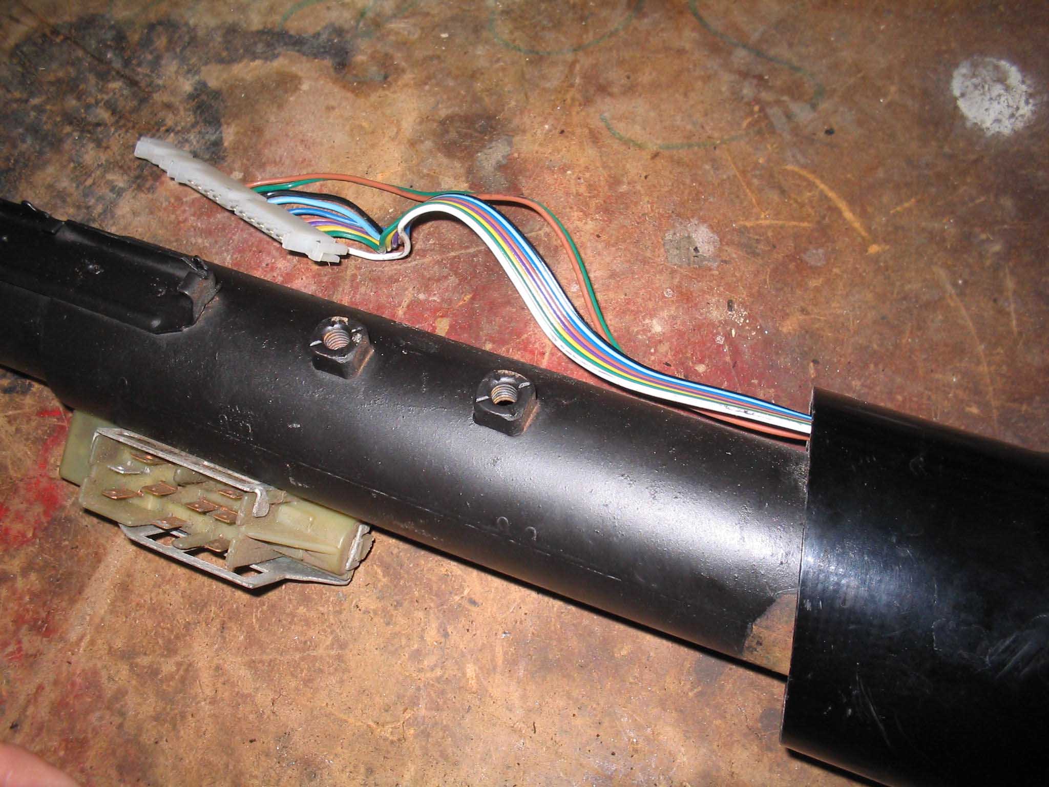
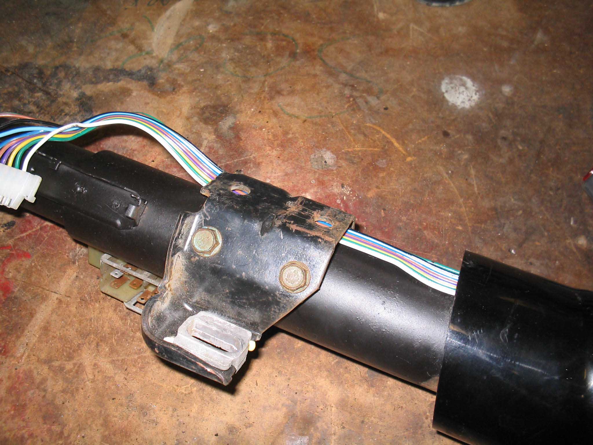
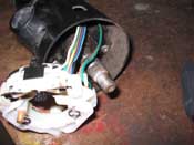
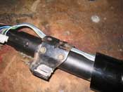
The wires can be contained inside the bracket that holds the column up to the top
of the dashboard. Simply put it behind the bracket and put the 4 bolts on.
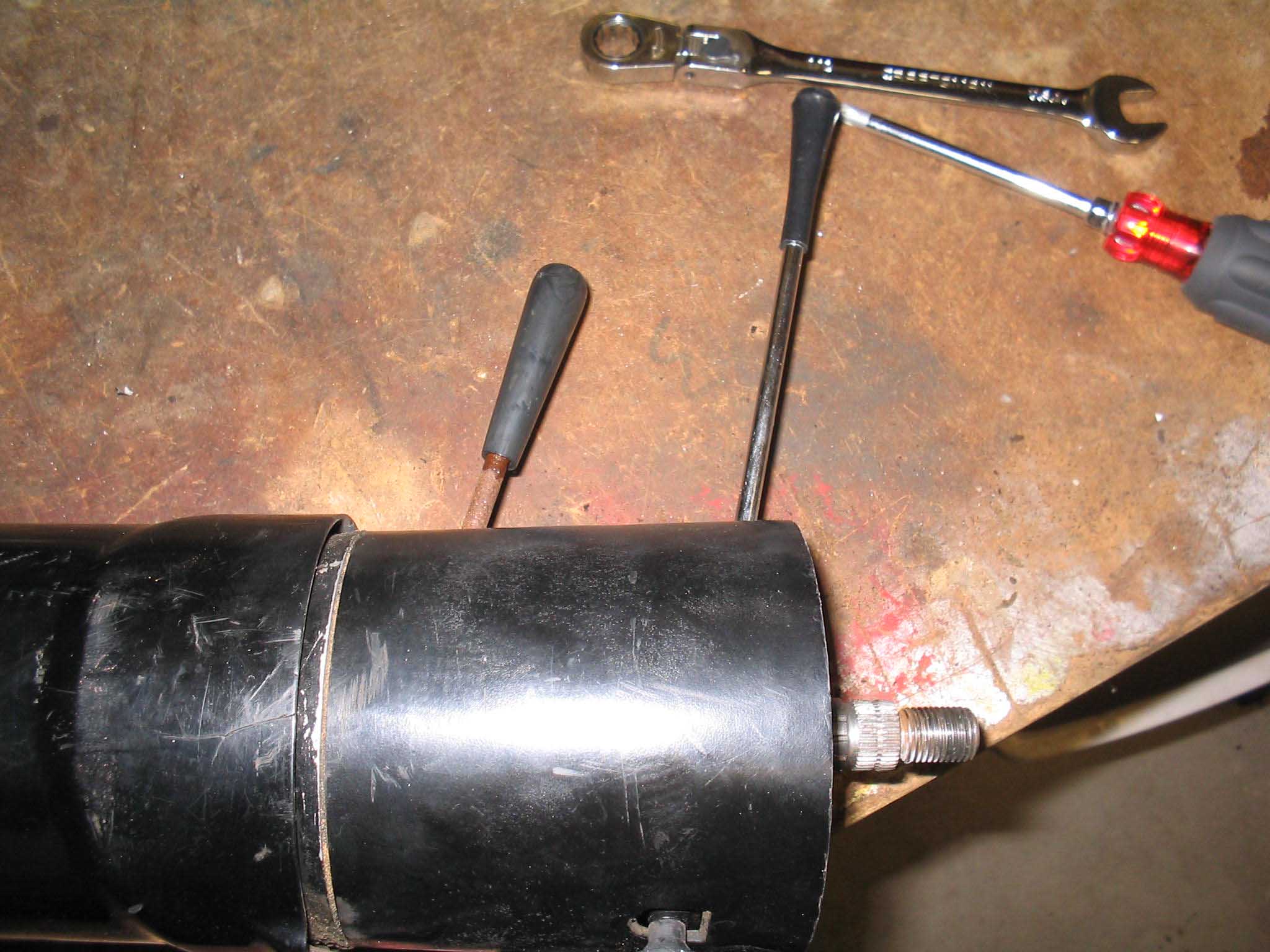
The turn signal lever as well as the tilt levers are next. They go on pretty easily. The tilt lever screws in, while
the turn signal lever goes on with a screw and it goes into the turn signal switch.
With all that in place, you are ready to put the column back together and hold everything in place.
|
| |
|

|
|

|
| |
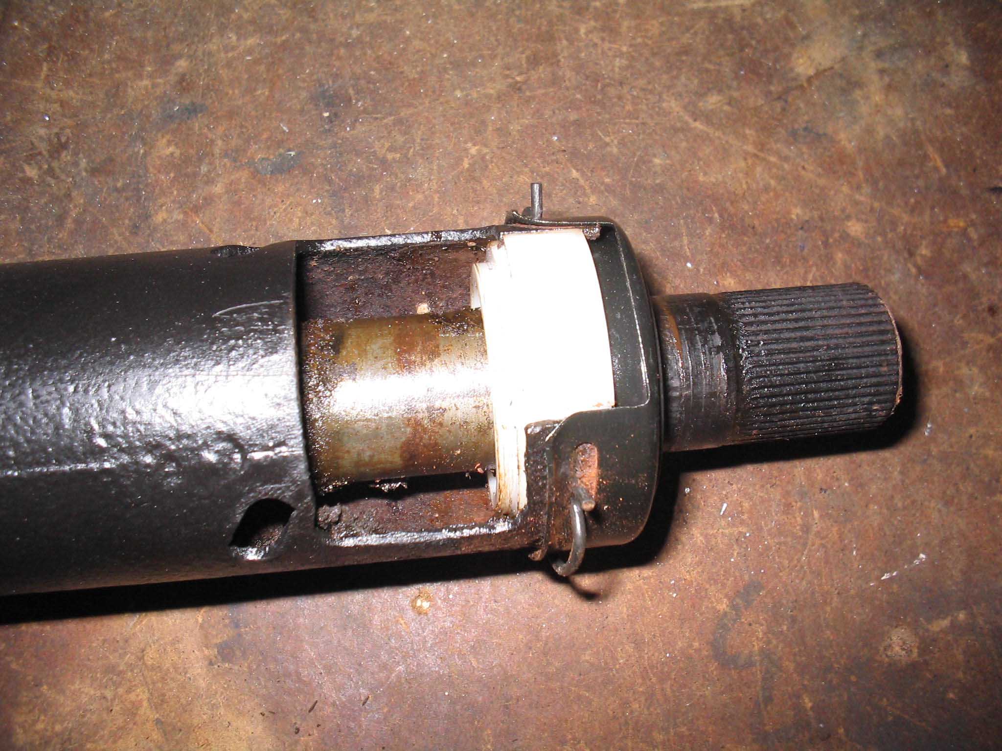
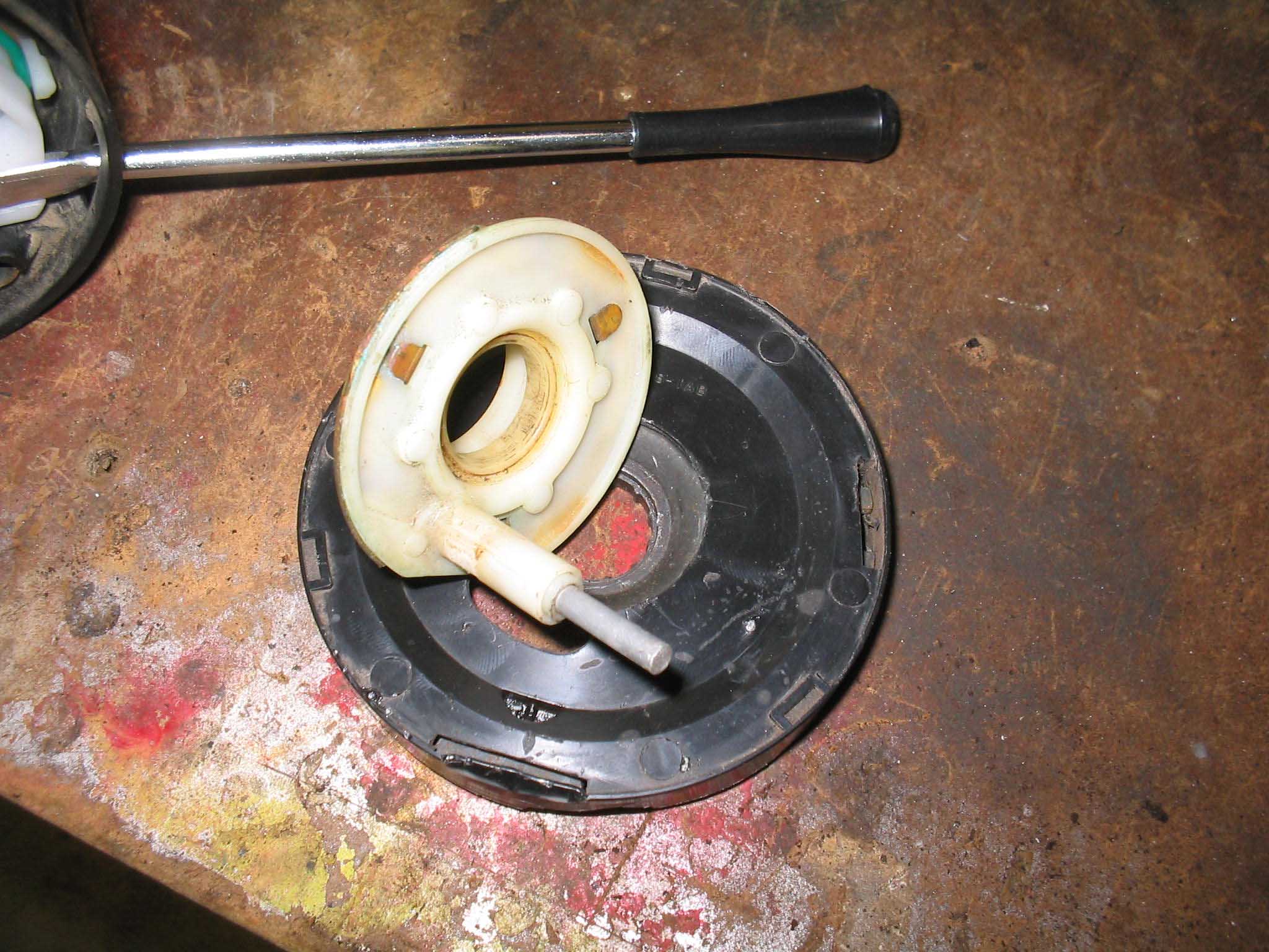
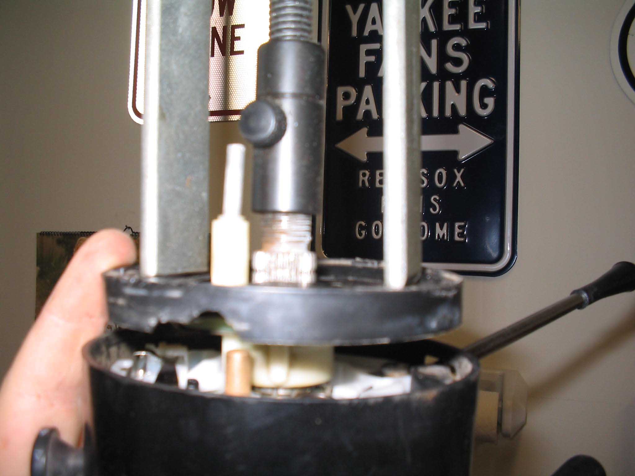
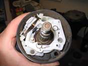
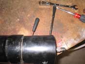
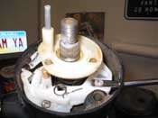
The spring goes on next and then the cancel cam / horn transmitter as well as the
ring that hold it all in place goes on the shaft and finally the tool that is shown can be used to compress everything
together. Once it is all pressed down, it can be clipped in place and released.
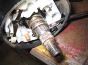
For those of you who are especially keen, you can see that the cancel cam shown is for a NON-TILT column. I didn't
have the new cancel cam when I shot the pictures, so I had to show the old one for display purposes. It all goes
together the same way regardless of cancel cam type.
cb (04/27/07)
|
| |
| << Previous |
| |
|