|
|
| Project "Free Jeep" a.k.a Project "FJ" - part #10 |
| |
|
1
2
3
4
5
6
7
8
9
10
11
12
13
14
15
16
17
18
19
20
21
22
23
24
25
26
27
28
29
30
31
32
33
34
35
36
37
38
39
40
41
42
43
44
45
46
47
48
49
50
51
52
53
54
55
56
57
58
59
60
61
62
63
64
65
66
67
68
69
70
71
72
73
|
| |
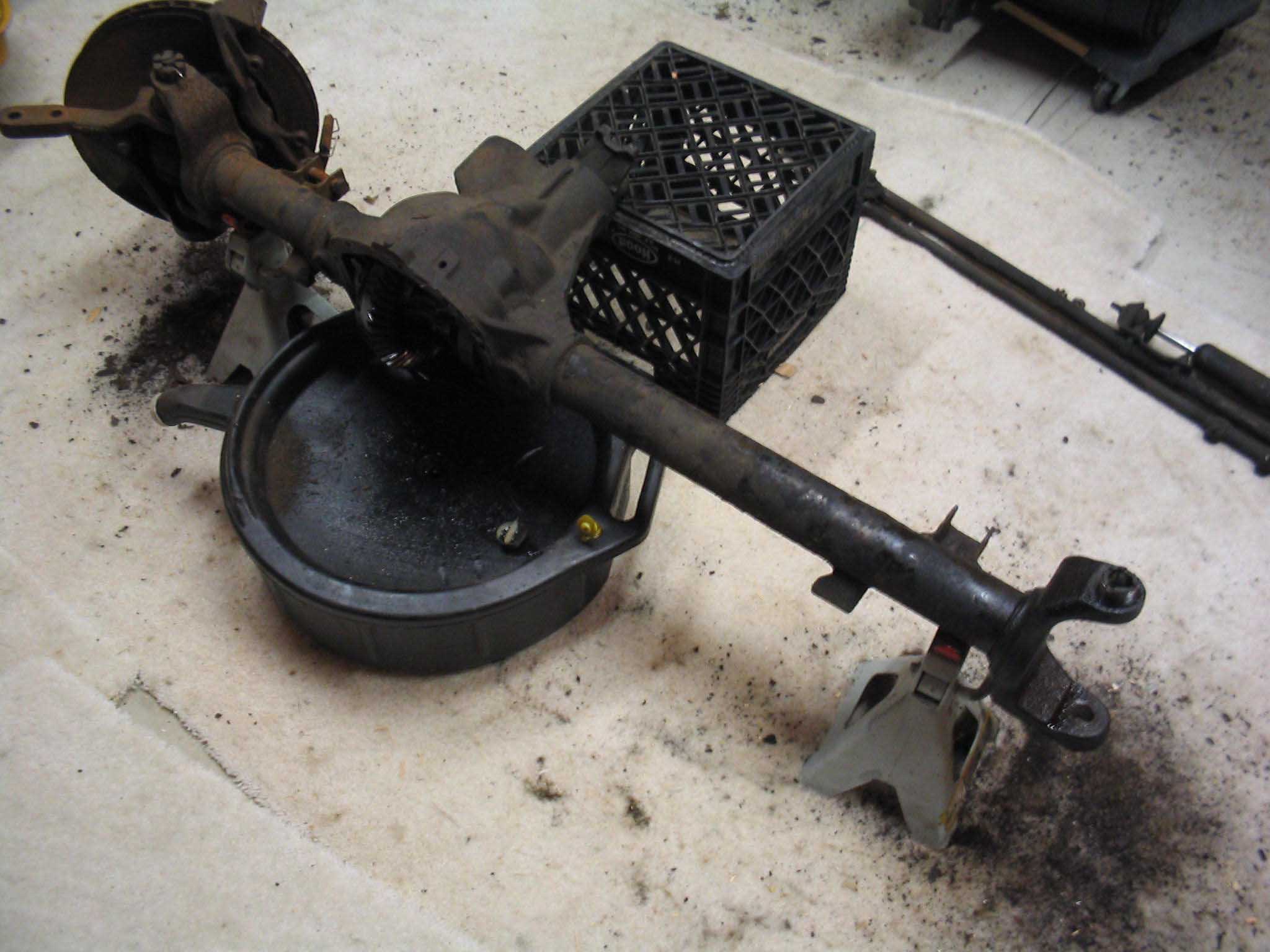
(11/28/06) So, continuing on with the axle tear down, I have ordered up all the new
parts and have started to tear down the rest of the axle. NOTE: Apparently the battery was running low
on the camera, so a few of the pictures are fuzzy and I apologize. I will try to update them with pictures from
the other side of the axle when I tear it down. This last teardown took a bit longer as I will explain in
the coming paragraphs, so I didn't get a change to do the passenger side yet.
So, this write-up starts off with basically needing to disassemble the entire side of the axle from the hub all the
way to the housing itself. Through the tear-down, lots of tools are necessary to get this thing apart, some even
specialty tools that if you haven't done this before, you need to get or you will be tearing your hair out.
|
| |
|
|
|

|
| |
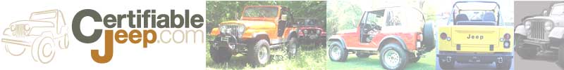
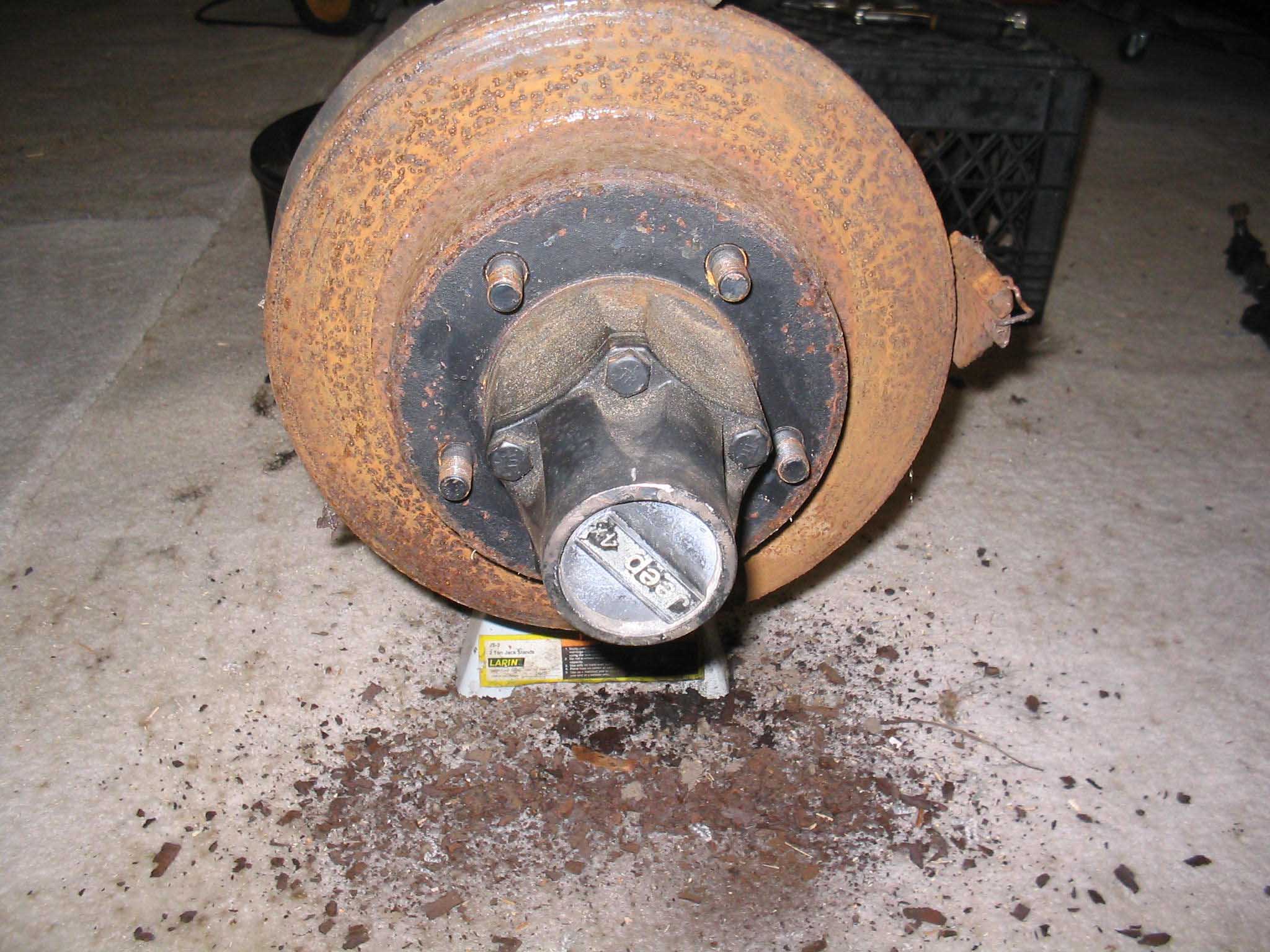
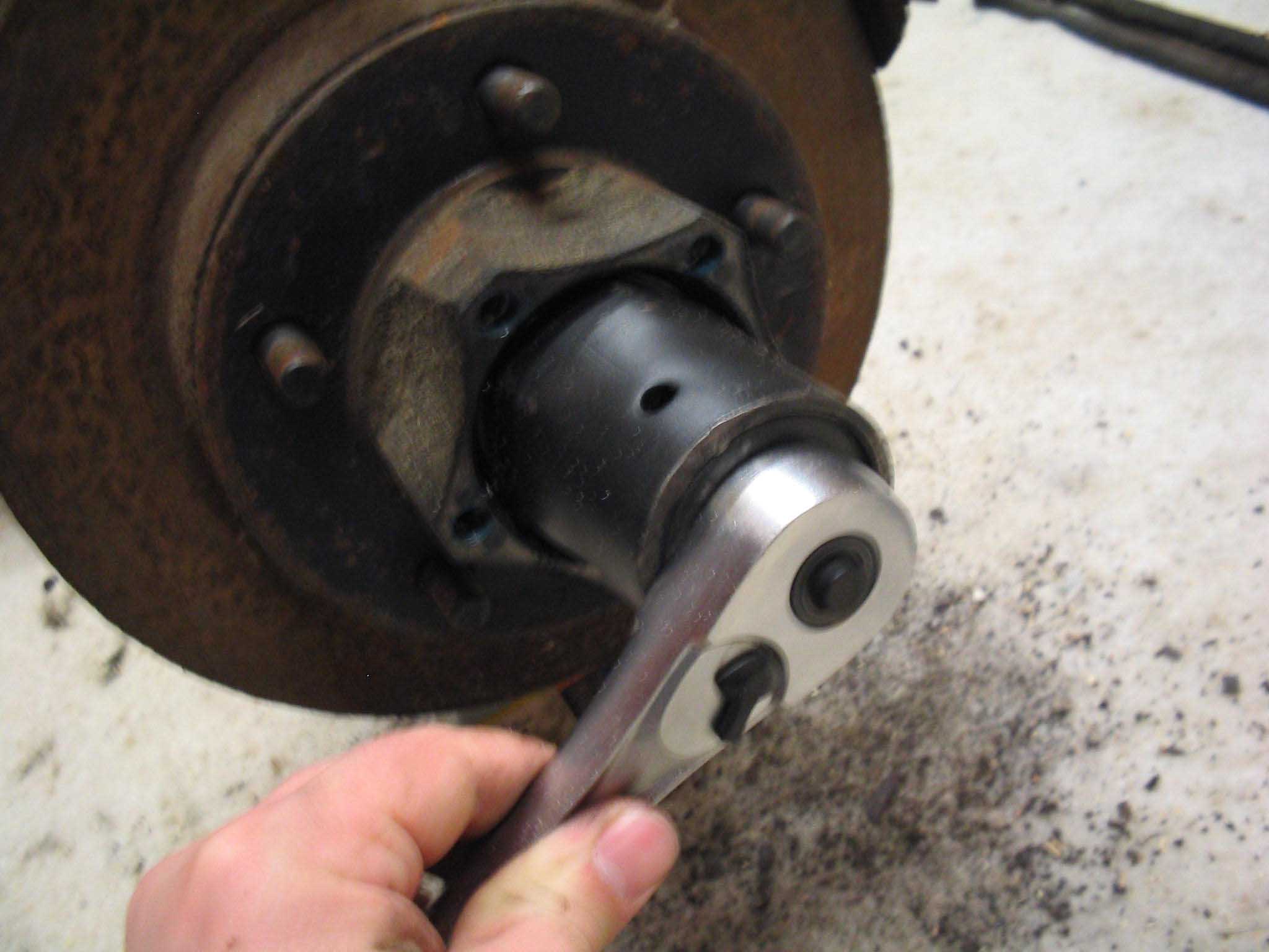
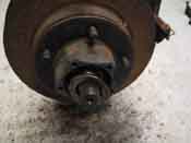
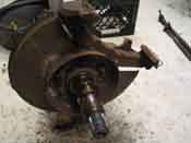
There are 5 hub bolts holding the locking part of the hub onto the hub of the
rotor. These were held in with thread lock, so you need to lock the rotor from spinning when trying to get the
bolts out. I stuck a screwdriver in the rotor and it braced itself against the caliper mount, it worked, can't
complain.
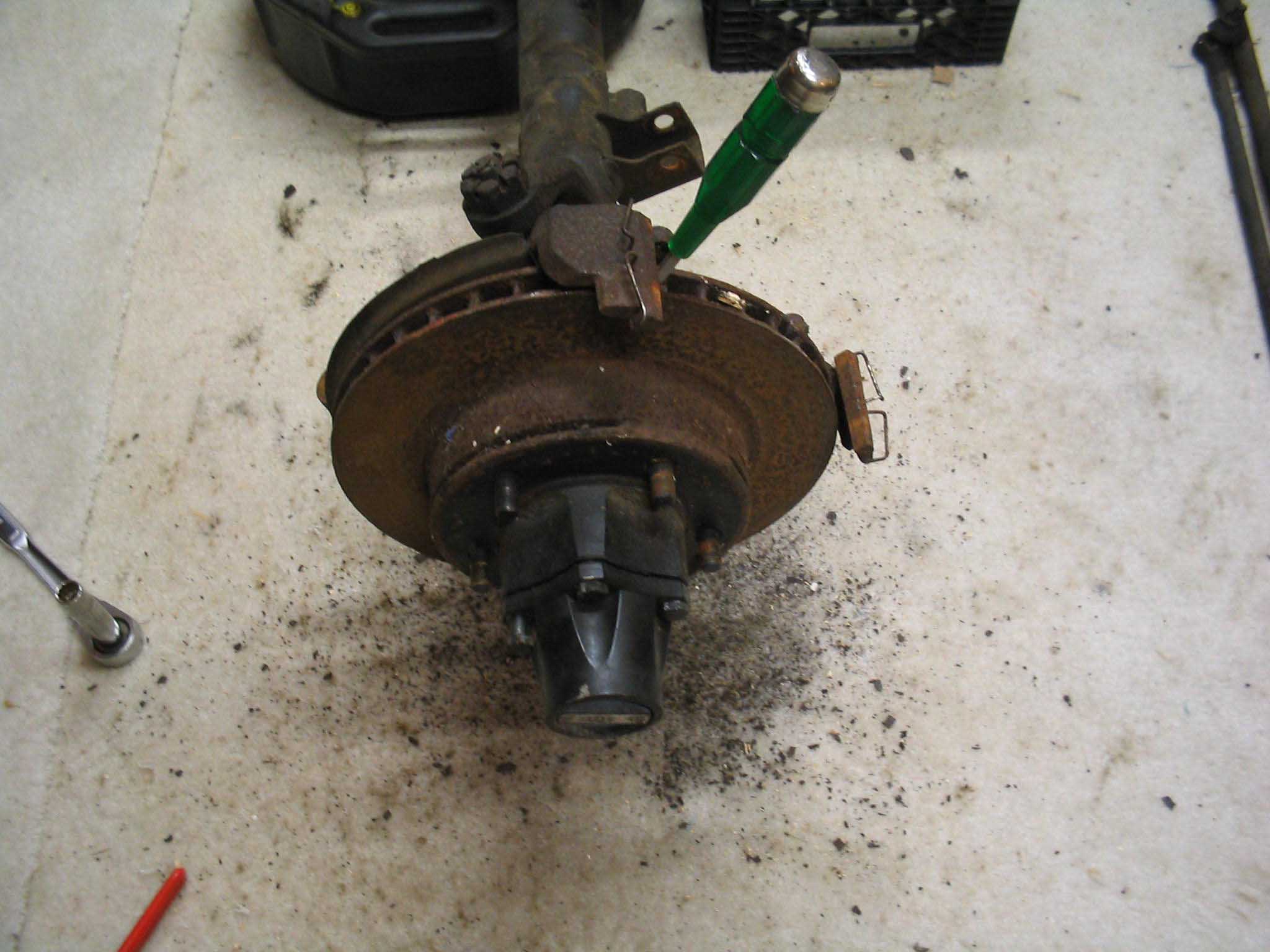
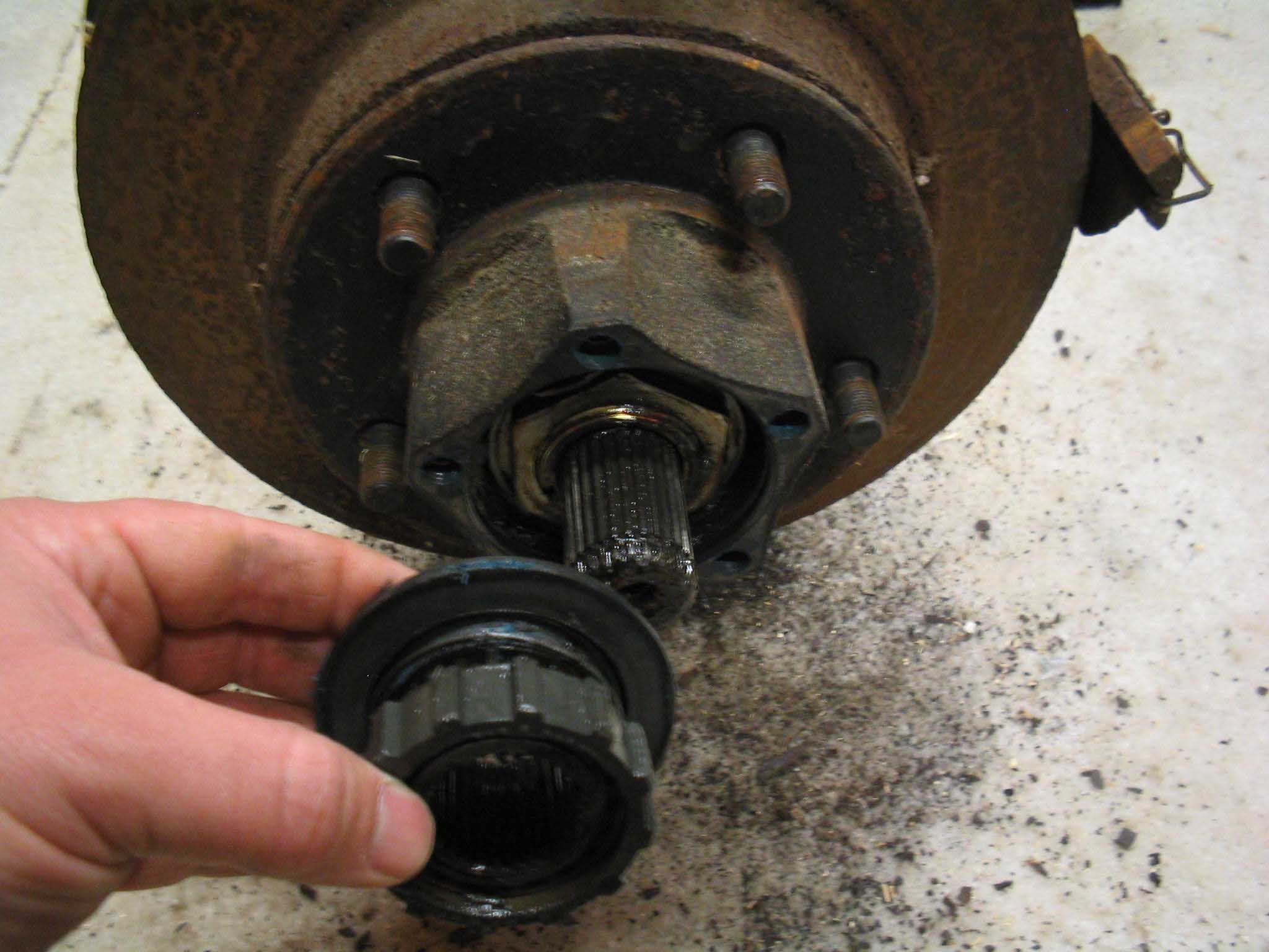
Once the bolts were out, the cap slides off. I had it in 2-wheel drive, but I don't think it matters. With the
hub removed, you can see the snap ring that holds the whole mechanism on. With a pair of snap ring pliers, remove
the snap ring and slide off the internal hug assembly. NOTE: I put all of these parts back in the way
they came out, so you can see now they go back together. You don't have to do this; it just makes it easier for
me. Also, I put them on the bench, out of the way of feet and swinging implements. Snap ring pliers can be
purchased at any hardware store. If you don't want to use them, you can use some pliers and a screwdriver to
get it off.
|
| |

|
|
|
|
| |
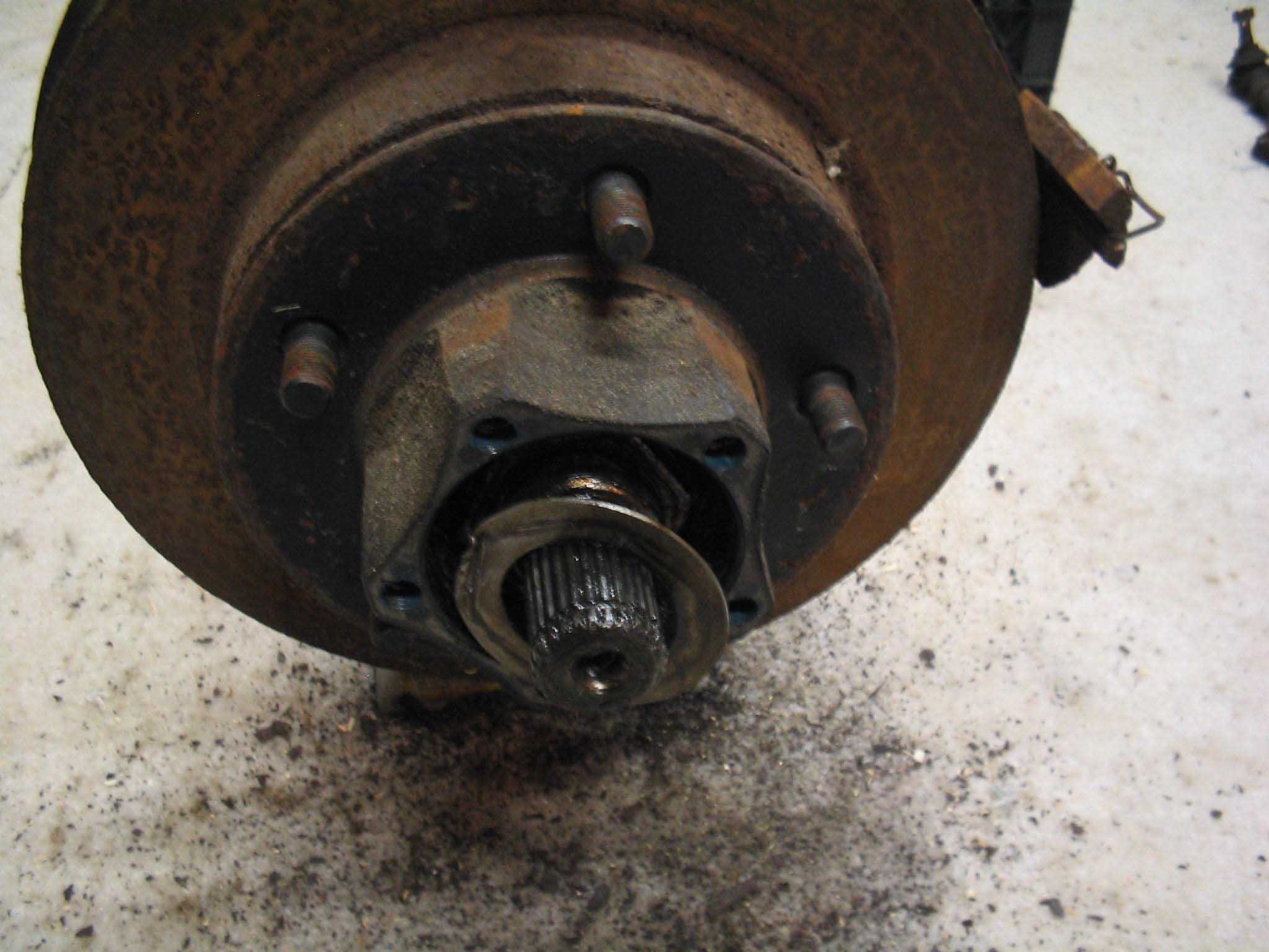
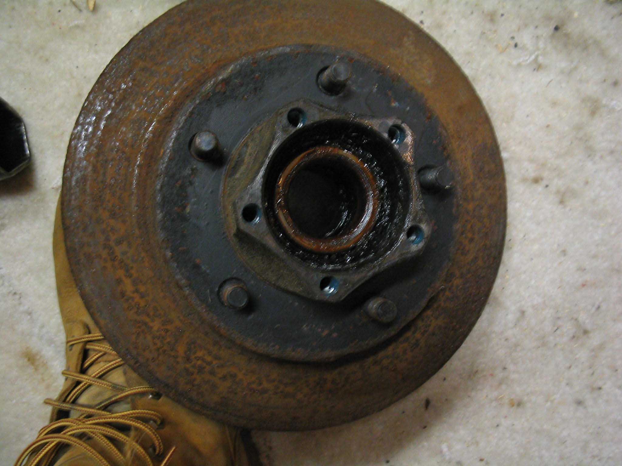
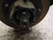
Next is another special tool I told you about. Holding the rotor onto the spindle
are 2 hex nuts and 2 washers. The outer most washer has a part that is bent over the hex nut causing it to stay
put. You have to bend this tab, use the special sized socket, remove the first nut, then the washer, then the
second nut, and then the last washer. They have groves in them as well to slide along the spindle. I used a magnet
to remove the washers, as it was easier to get them out with all the grease that was on them.
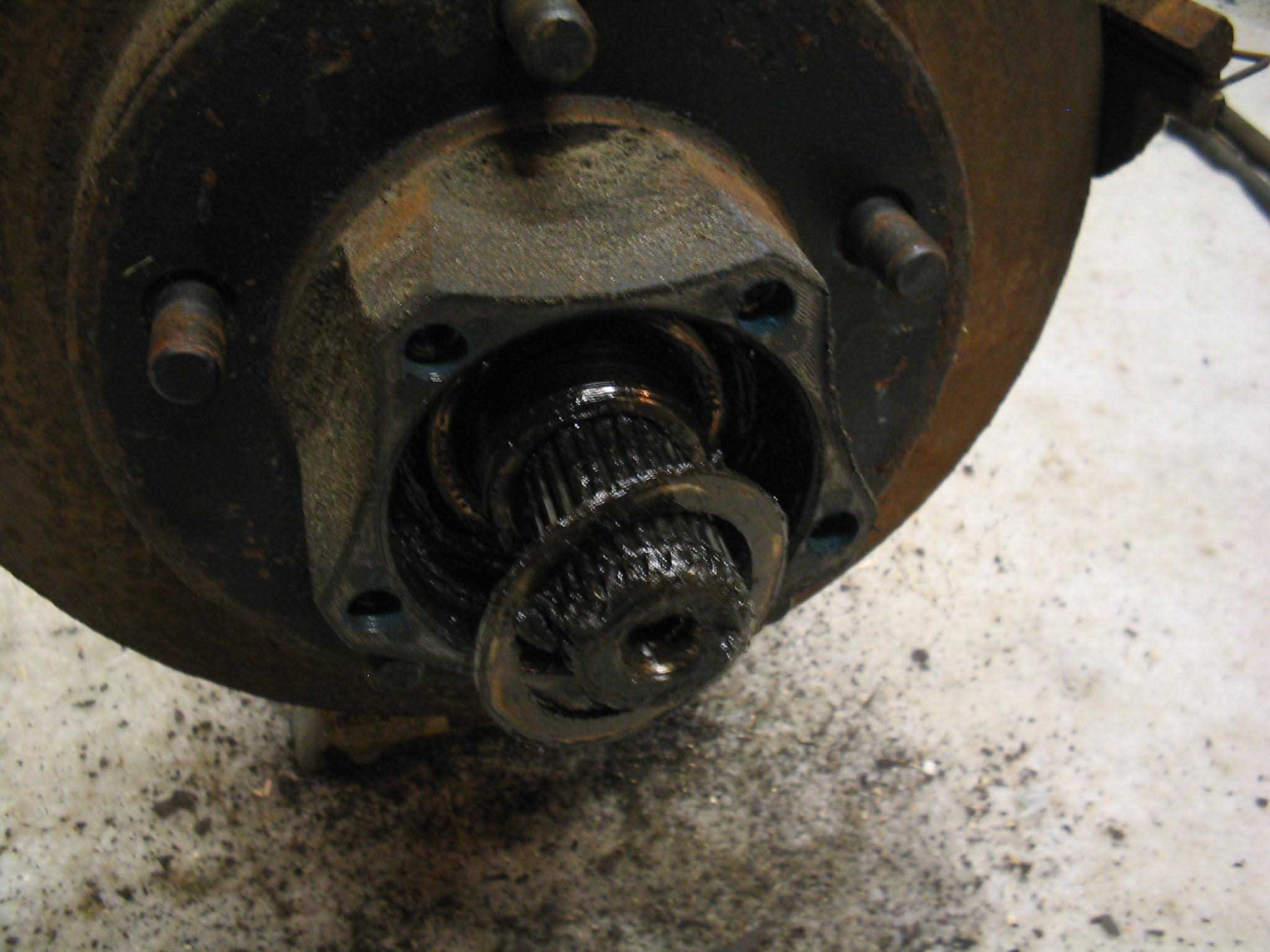
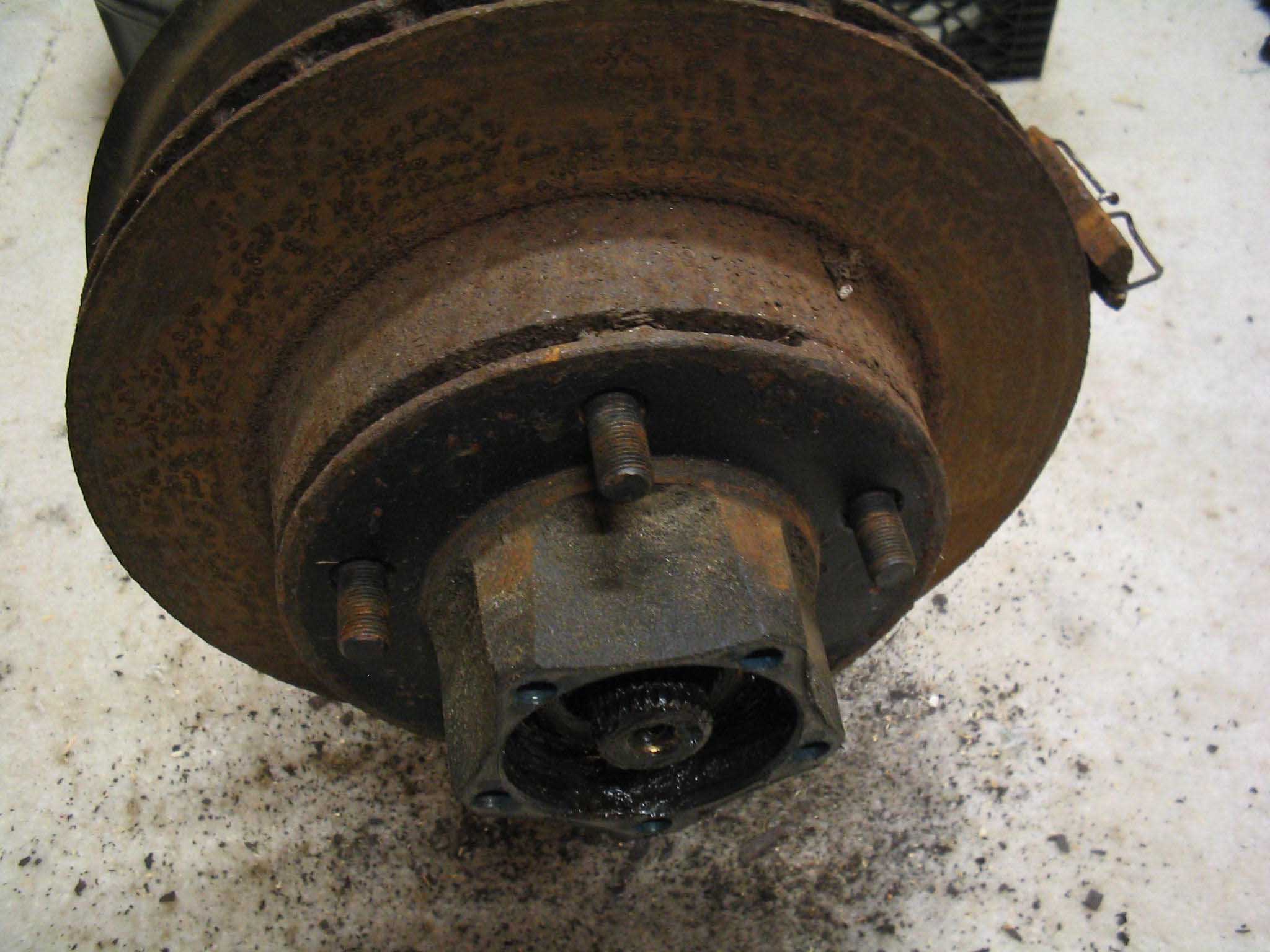
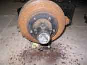
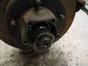
With all the nuts and washers out, the whole rotor/hub assembly should just slide right off. Sometimes
it needs a little tap with the hammer. In this case, it slid right off. Something to note that was good was
that there was a lot of grease still inside the bearings, inside the rotor/hub assembly and as well on the
spindle. This is a good sign even though it is messy. You may also notice that the rotors are rusty, but
actually could probably be turned down and used again. I am going to replace everything for this build, but it is
worth a shot to take them down to a Midas or someplace that turns rotors and see what they can do for you. New
ones run about $20.00 each, so for this build-up I will go with new ones.
|
| |

|
|
|
|
| |
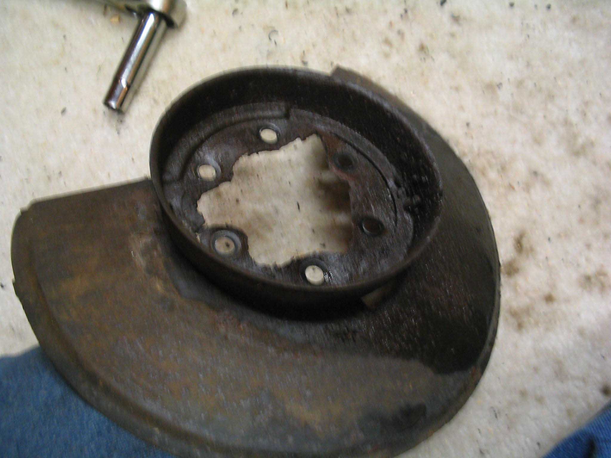
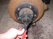
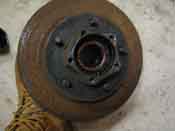
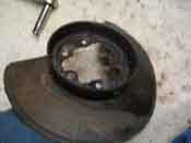
With the whole assembly off, you are left with the brake dust shield. Usually,
these are rusted in place, which makes it a PITA to remove. I soaked the 6 9/16" nuts with penetrating oil, heated
them up a bit and then most of them came off without an issue. Sometimes they don't want to come off, so I back
them off as much as they will come, then back them down, spray more, wire brush on the threads, and do it again.
After a few times of this, they come right off, but they are usually really hot, so use some gloves!
So, as you can see, the dust shield is toast. Toss this aside and get some new ones. They are like $20.00 a
piece as well.
|
| |
|
|
|

|
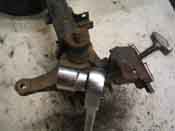
| |
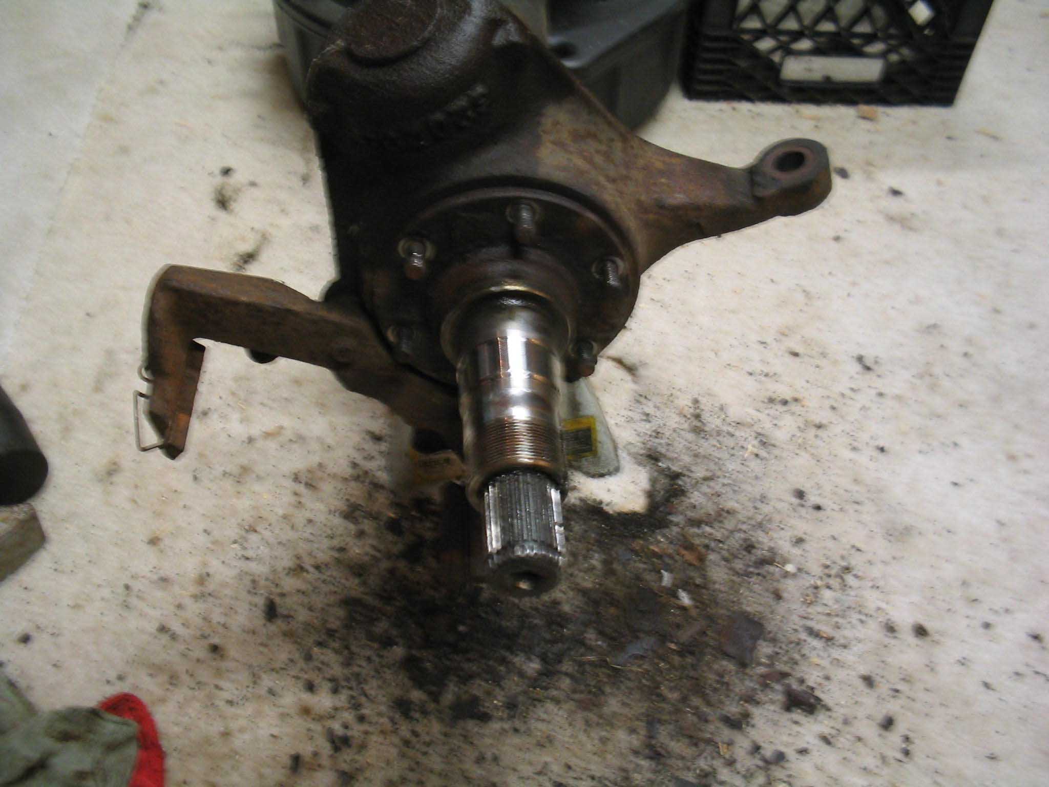
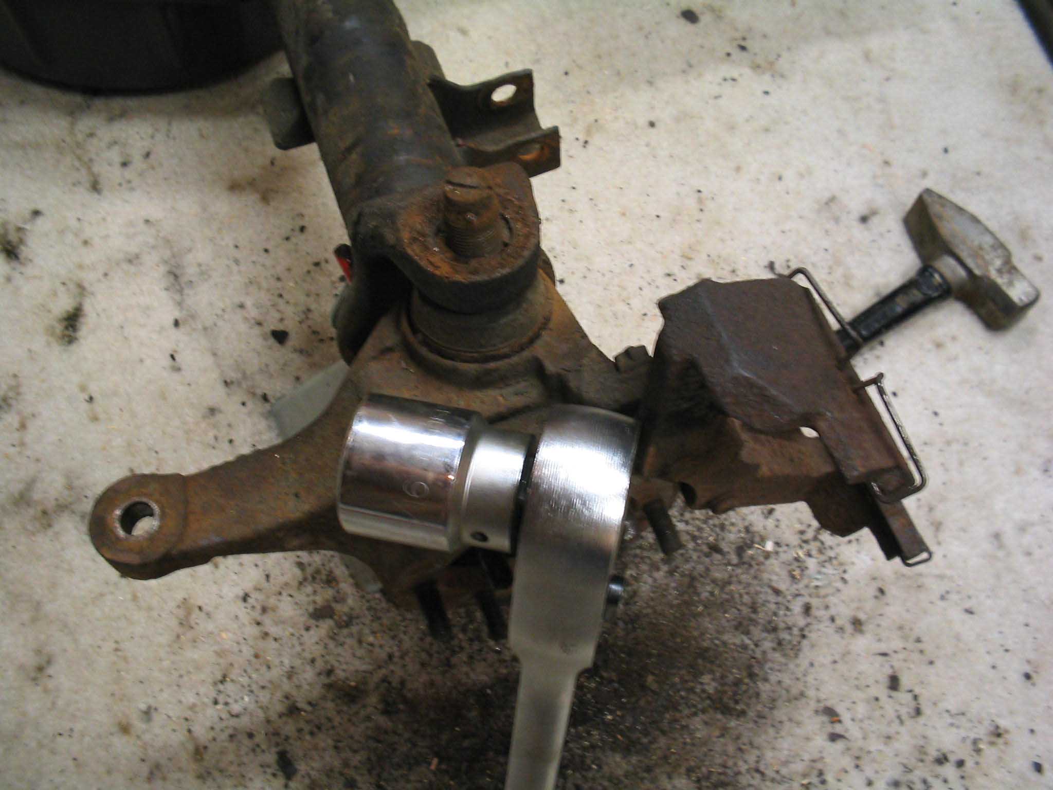
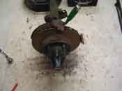
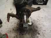
Next is the spindle, and for some reason, usually the hardest piece to get off.
This one was no exception; it was rusted in place and didn't want to move. So, what I did was take a rubber
mallet and whack it a few times to loose it up. This worked a bit and what I had to do was pry off the rest of it
with a hammer and screwdriver to separate the spindle from the knuckle. It was really rusted on as well
as just they years of torquing it in place really caused it not to come off. Once I had about 1/2" separation of
the spindle and the knuckle, I used a tie rod separator and just wedged it in there to get the rest of it to
separate. I have never seen the tie rod approach before, but it seemed to work and the spindle was separated
from the knuckle.
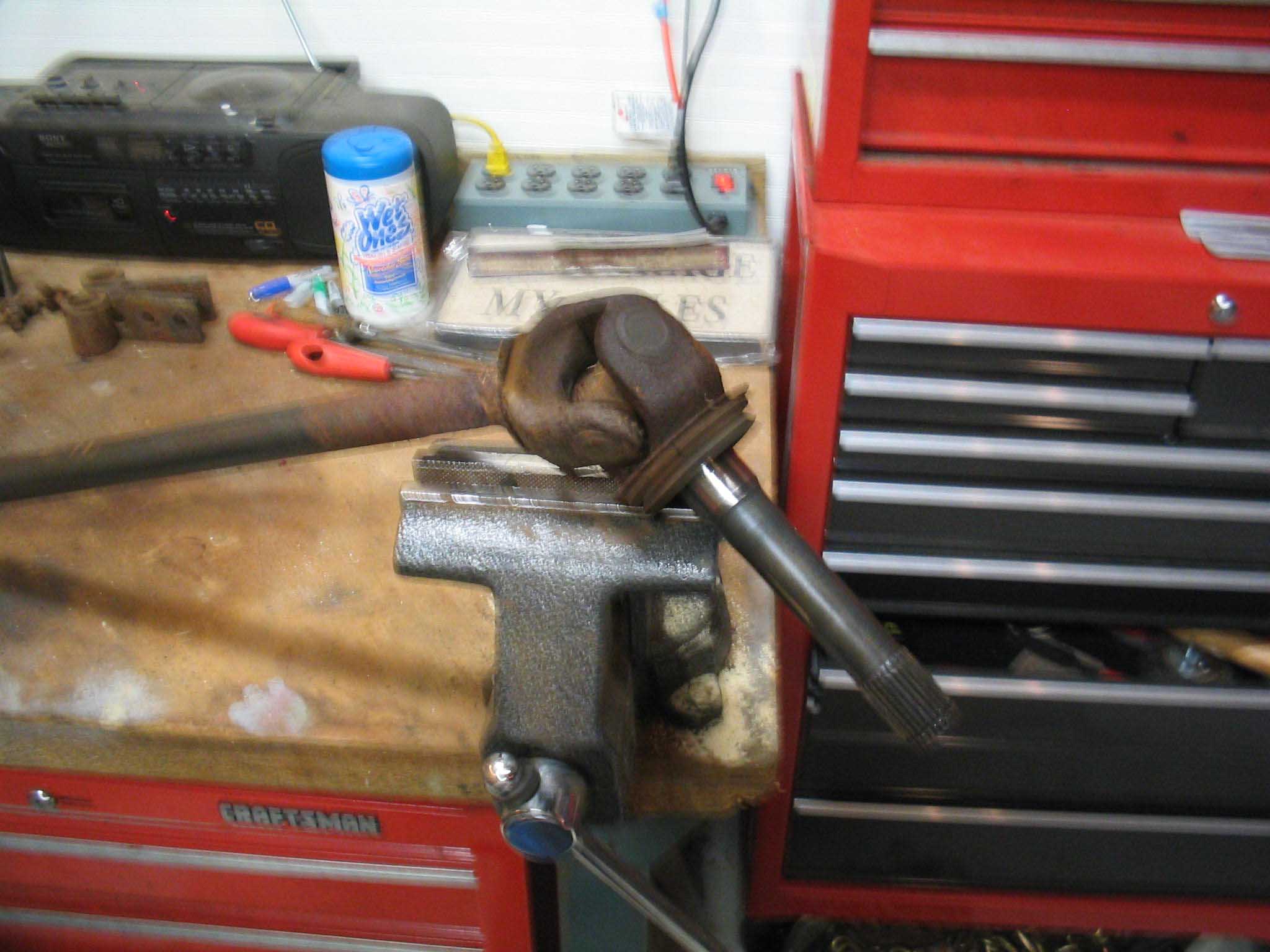
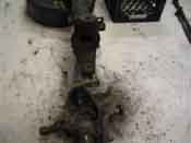
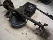
With the spindle off, the axle slides right out and you are left with the knuckle on the housing attached with the
ball joints. The u-joints in the axles were toasted big time and need to be replaced. I need to get a press
to get them out as I tried the vice approach with the 2 sockets and that didn't seem to work, so I need to
try something else. But, I am babbling, so back to the disassembly...
|
| |
|
|
|
|
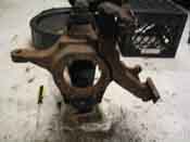
| |
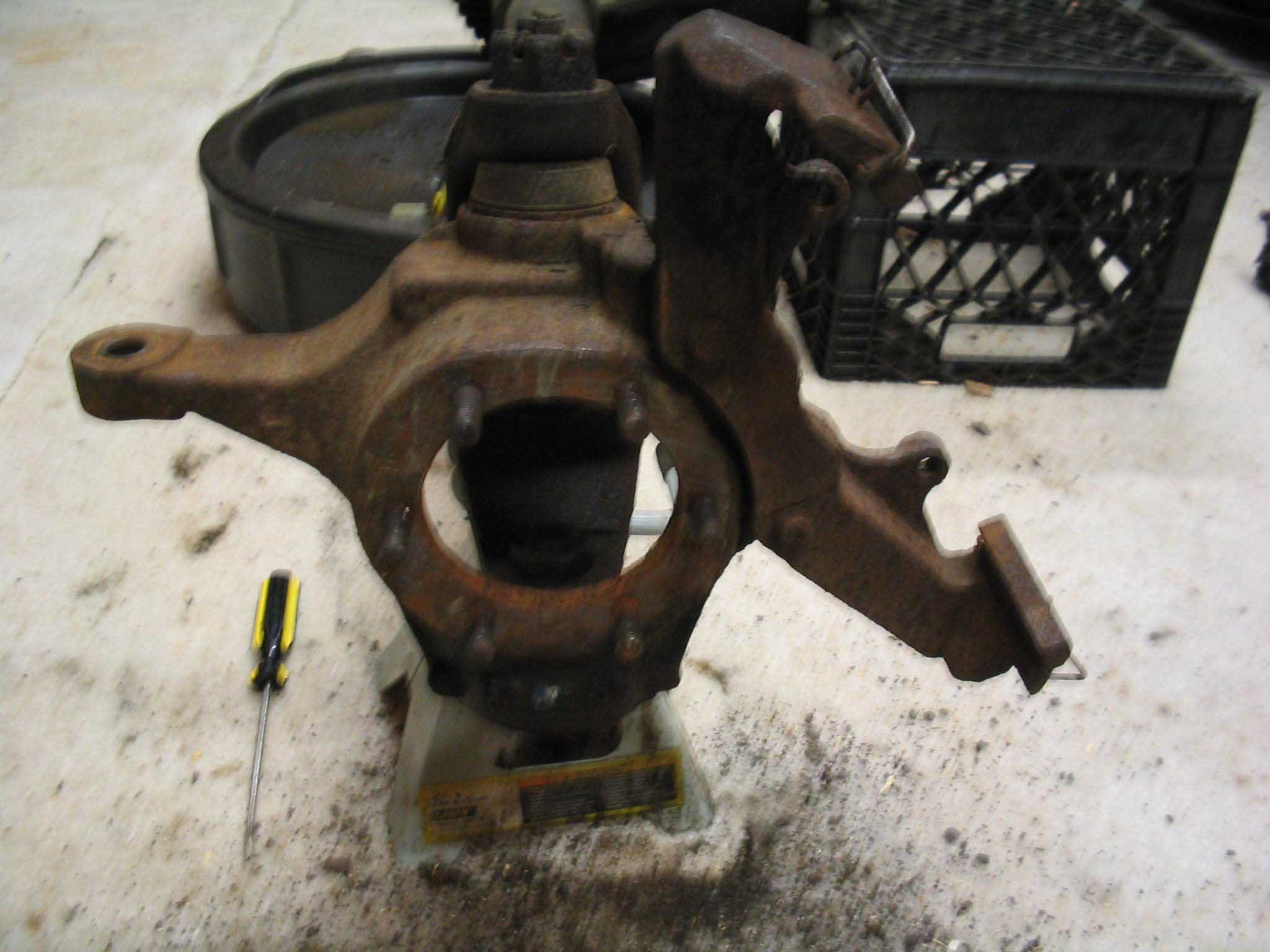
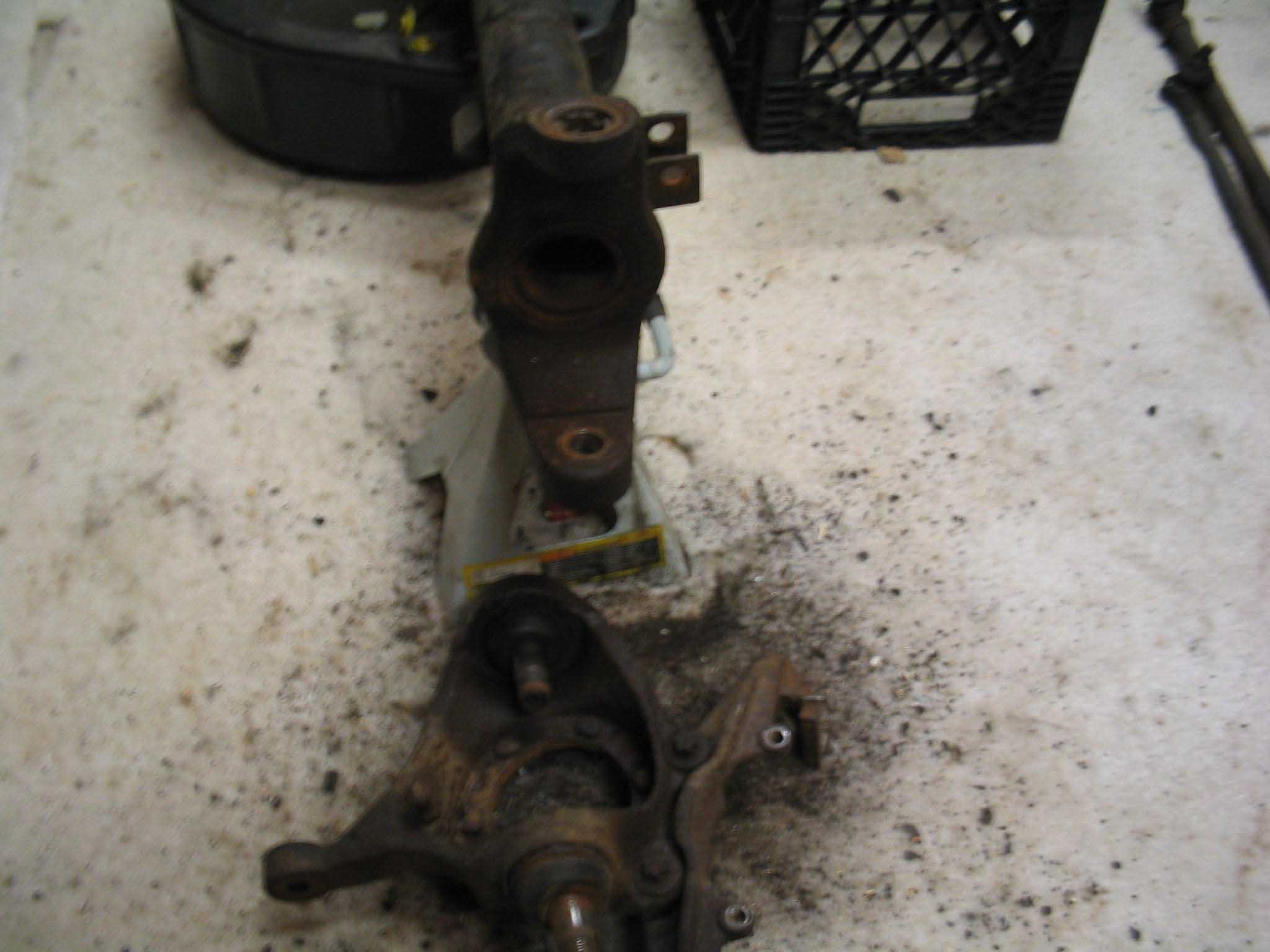
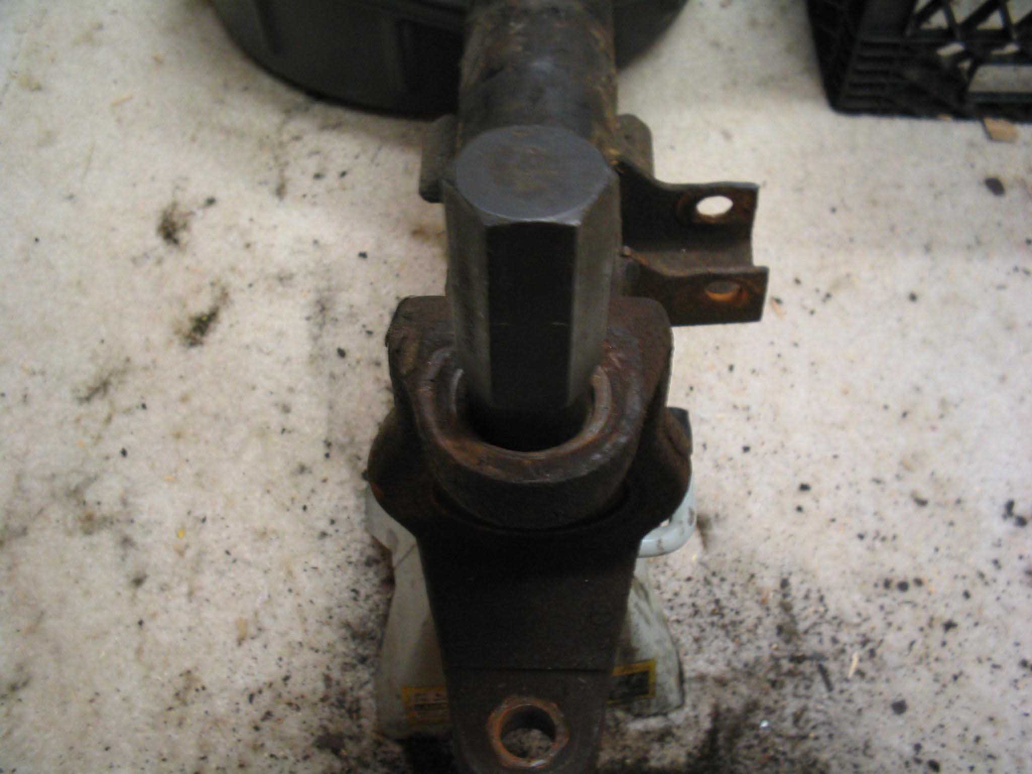
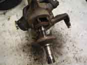
Last to come off is the knuckle, and that is held in place with 2 nuts, one on
top and one down below, inside the knuckle. They are different sizes, so be aware of this as well as be aware
that they are on there tight, so you will need something to help give you a little leverage, plus someone
to hold the axle if possible. One more thing to note here, the not nut is larger then a standard socket set, so
you might have to get one. I am not sure the exact size, but I know that I went to my 3/4" set to remove it after
the cotter pin was removed.
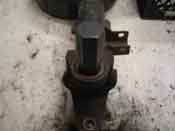
Since I am going to replace the ball joints, as I knew that they were shot, use a BFH to knock out the ball joints.
My 3 pounder knocked it out with a few whacks and I was finally done with the removal of all the components on the
driver side. The last part to come out is the split sleeve that gives the pre-load on the knuckles with the
ball joints. This also is a special tool with a castle cut sort of on top of it. You can get this at a
variety of places like 4wd, Quadratec, etc. Once that is removed, the passenger side needs to be done and then
we can move onto cleaning up the axle, sand blasting it, painting it, and finally putting it all back together
and then move onto the rear axle.
These are the basic steps for removing all the parts. It takes some special tools and a whole lot of time and
patience. Took me about 3 hours from start to finish to remove it and document the whole process. I had some
trouble with the spindle and the dust shield as they were in rough shape. Also, I cleaned up a lot of the parts
that will be re-used, as they will be painted to boot. This should take a couple hours to complete if you are
doing it on the Jeep. Be prepared to not finish though if you run into issues.
cb (11/28/06)
|
| |
| << Previous |
Next >> |
|